Provide customized design one-stop service
Nov. 12, 2026
Share:
When selecting a titanium porous transport layer for a PEM electrolyzer, start with the two surfaces it touches: the anode flow-field plate and the catalyst layer. The PTL must deliver water, remove oxygen and maintain electrical contact under assembly pressure. Samples with the same nominal thickness can behave differently at these interfaces.
A titanium porous transport layer (PTL) is a porous, electrically conductive component on the oxygen-producing side of a PEM water electrolyzer. One face contacts the anode catalyst layer. The other spans the flow channels and touches the raised sections of the plate, called lands.
The pores provide paths for water and oxygen, while the solid titanium provides a path for electrons. For an overview of the cell and its components, read Gitan’s guide to PEM water electrolysis.
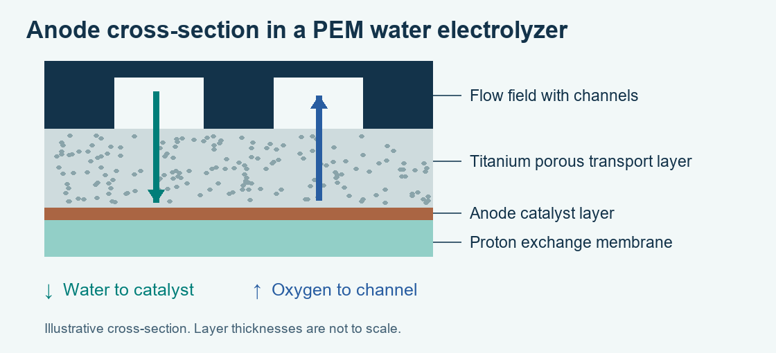
Figure 1. Anode cross-section. Channels supply water and collect oxygen. Layer thicknesses are schematic.
H2O Water delivery. Feed water passes from the channels through connected pores to the anode catalyst. Beneath a plate land, water may also travel sideways. Evaluate a PTL together with the intended flow-field geometry.
O2 Oxygen removal. Oxygen forms at the catalyst surface and exits through the pore network toward the channels. Water supply and oxygen removal share this network, so pore connectivity matters.
e- Electron conduction. Electrons released at the anode travel through solid titanium to the plate. Contact area and surface condition at each interface influence electrical losses.
Ask what the supplier means by titanium mesh. Woven wire mesh, expanded metal and multilayer sintered mesh have different geometries. The illustration below shows woven mesh. For multilayer material, specify the construction of each layer and identify the face that contacts the catalyst.
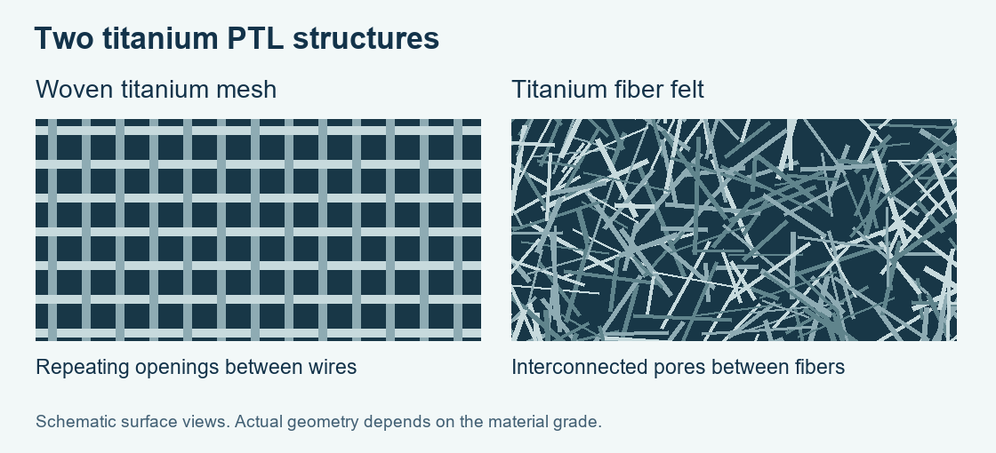
Figure 2. Illustrative surface views of woven mesh and fiber felt. Actual pore dimensions and surface finish depend on the material grade.
| Feature | Woven titanium mesh | Titanium fiber felt |
|---|---|---|
| Geometry | Request wire diameter, aperture, weave and layer count. | Request fiber diameter, pore-size distribution and thickness tolerance. |
| Catalyst-facing surface | Check wire crossings, opening span and any finer facing layer. | Check surface finish, exposed fibers and whether the two faces differ. |
| Assembly trial | Check edge finish, orientation and support across the plate channels. | Check compressed thickness and inspect the catalyst-facing surface after representative assembly. |
Compare measurements made under equivalent conditions. A mesh aperture and a felt’s mean flow pore size describe different features even when both are expressed in micrometers. Contact resistance also depends on the counterface and applied pressure.
| Parameter | Why it matters | What to ask the supplier |
|---|---|---|
| Thickness | Assembled thickness affects fit, contact and gasket compression. | What are the free thickness, tolerance and thickness at our assembly pressure? |
| Porosity | Void fraction describes available space. Transport also depends on connectivity. | Is this total or open porosity? Which method and sample condition were used? |
| Pore size | Openings and constrictions affect water delivery, oxygen removal and catalyst support. | Is the value mesh aperture, mean flow pore size or a distribution? What was the measurement method? |
| Contact resistance | Interface losses depend on surfaces and compression. | Can you provide area-specific contact resistance at several loads, with the counterface material and finish? |
| Surface treatment | Oxides and coatings influence contact. Treatment may differ between faces. | Which face is treated and with what material? Are measurements available before and after durability testing? |
Send the active area and outline drawing separately. An active area of 50 cm2 gives the supplier the electrode area. The drawing adds finished dimensions, edge clearances, cut-outs and orientation. Include the assembly pressure, contacting materials and required sample quantity.
We are evaluating [woven titanium mesh / titanium fiber felt] for the anode of a PEM water electrolyzer. Our active area is [cm2], and the attached drawing gives the finished dimensions. The target thickness is [mm] at an assembly pressure of [MPa]. The PTL will contact [plate material and finish] and [anode catalyst layer]. We need [quantity] samples. Please identify the catalyst-facing side and provide thickness tolerance, pore data and contact-resistance test conditions.
In this guide, PTL refers to the porous titanium component on the oxygen-producing anode. GDL means gas diffusion layer, a term used for porous media in fuel cells and sometimes on the hydrogen side of an electrolyzer. Confirm the cell side, material and contacting surfaces when reading a drawing.
No. A larger void fraction can leave fewer solid contact points at the catalyst surface. Compare water delivery, oxygen removal and electrical contact together using the intended plate geometry and assembly load.
Matching nominal thickness is the first check. Compare compressed fit, catalyst support and contact resistance. Before approving a substitution, evaluate both samples using the same CCM, plate, assembly pressure and operating conditions.
Review Gitan’s catalyst-coated membranes or contact Gitan about your PEM cell or CCM project. Include your active-area drawing, catalyst-facing material and intended assembly pressure so the team can review the interface.
Technical reading: Flow-field geometry and PTL properties and the effect of compression on PTL performance.
Need Custom Design and Development for CCM And PEM Electrolyzers?
We strongly support customer personalisation and customisation, providing the most suitable solutions based on different customer needs. If you have any customisation requirements, please contact us and we will provide you with the most professional advice and products.
View MoreRelated Products
We R&D, design, manufacturing and sales of PEM membrane electrodes, hydrogen and oxygen electrolytic cells and other ancillary products.
alkaline water ionizer J001-5P 5plate
The J001-5P Electrolyzer is a compact, high-performance water electrolysis system designed for reliable hydrogen production. Featuring a platinum coating, dual-side coating for easy reversal, and adjustable flow and pH levels, it offers efficient and stable output with enhanced durability.
A400D‑2200 PEM Water Electrolyzer 400 mL/min Hydrogen Generator Module
The 400ml 200ml/layer series Single-Output Hydrogen-Oxygen Electrolyzer is composed of a stacked combination of dual-layer 200ml PEM proton exchange membrane.
Compact Electrolyzed Alkaline Water Module with Pure Titanium Electrodes – Three-Button Design
The Three-Button Electrolyzed Alkaline Water Module is designed for producing purified alkaline water with PH levels of 8.5 and 9.5. Using a flow sensor and TDS monitoring system, this module adjusts the electrolyzer’s power to produce alkaline water at the cathode and acidic water at the anode.
Low-Maintenance PEM Hydrogen Module for Water Dispensers
The 1500ml 250ml/layer series Single-Output Hydrogen-Oxygen Electrolyzer is composed of six layers of 250ml PEM proton exchange membranes stacked together.
Hydrogen-Rich Drinking Water Bottle with Proton Exchange Membrane (PEM) SPE Electrolyzer Technology
The hydrogen-rich water cup module, Using self-developed chemical deposition method PEM proton exchange membrane, the quality is stable and reliable
Alkaline Water Module for RO Systems | Enhance Your Water Dispenser with pH Balance
The Three-Button Electrolyzed Alkaline Water Module is designed for producing purified alkaline water with PH levels of 8.5 and 9.5. Using a flow sensor and TDS monitoring system, this module adjusts the electrolyzer’s power to produce alkaline water at the cathode and acidic water at the anode.
200 Nm³/h Industrial PEM Electrolyzer Stack with pure titanium plates for green hydrogen production. High efficiency, long lifespan and stable output for large-scale hydrogen plants.
J002-11P Alkaline Water Ionizer 11 Plates – Built-in Electrolysis Core for Dispensers
The J002-11P Electrolyzer is designed for high-efficiency hydrogen production with an 11-layer microfiltration membrane, platinum coating for extended lifespan, and dual-sided coating for superior scale removal. Its compact structure ensures stable and reliable performance, making it ideal for sustainable energy applications.